Dvi D To Vga Pinout Diagram
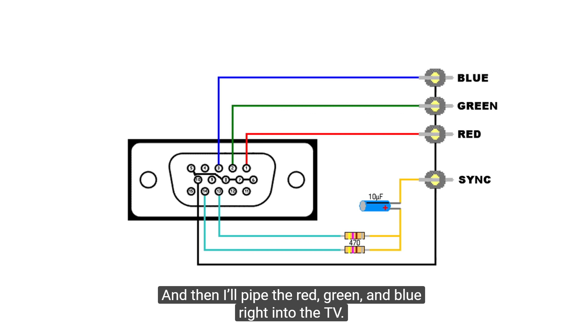
Pinout diagram of a VGA adapter, from Wikipedia. VGA Waveform Guide, from Altera. Given these five signals, we can divide each line into four distinct sections. During the first section (Vertical and Horizontal Syncs), the necessary syncs are driven low and RGB must be set to digital low, as well, for the monitor to observe the syncs correctly.
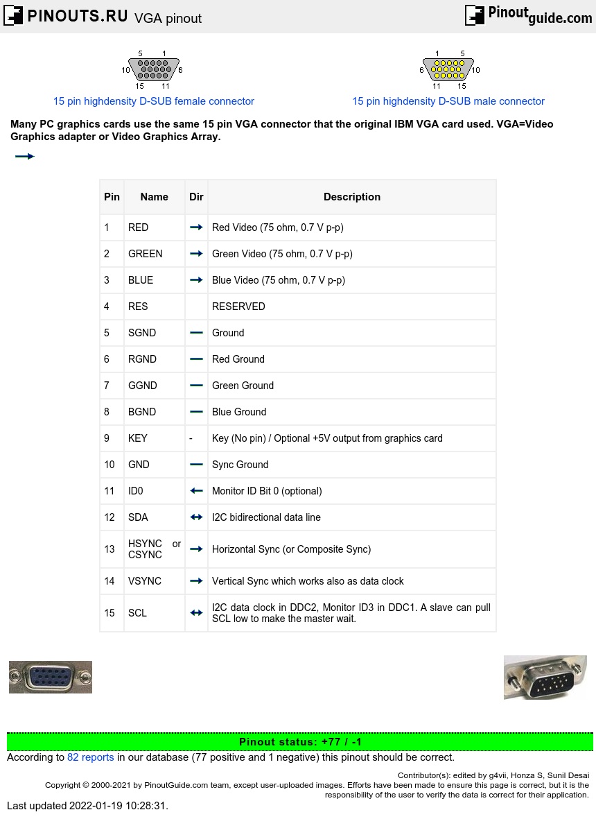
VGA pinout diagram
2 The Macintosh and monitors for it used a DB-15 connector similar to that of a game port. I wouldn't find it astonishing if there existed some PC graphics cards that used the same connector. - supercat
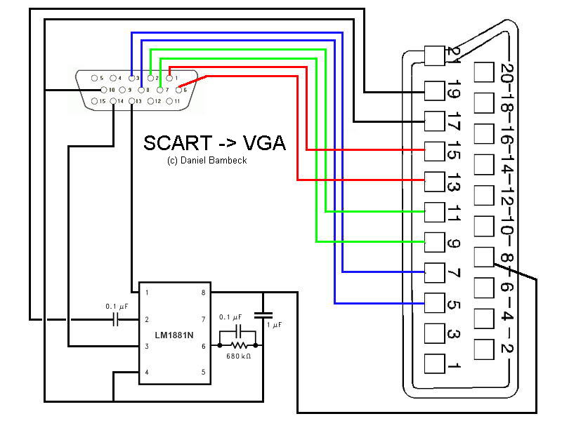
Scart 2 VGA Pinout cable and connector diagramsusb, serial rs232,rj45 vga, parallel
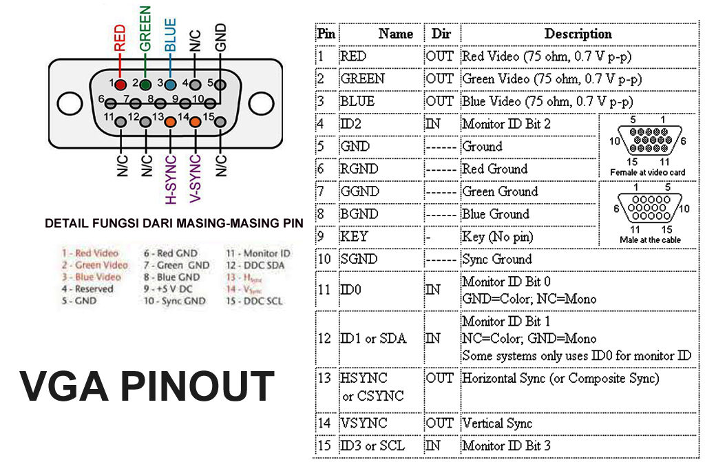
The VGA Interface bus uses either a 9-pin or 15-pin D-sub connector. The table below provides the pinout and signal names for either the DB15-pin or DB9-pin video connector. The connector may be advertised having a number of different options. Assuming a 15-pin VGA connector on both the Monitor and PC; the cable will indicate 15 pins.
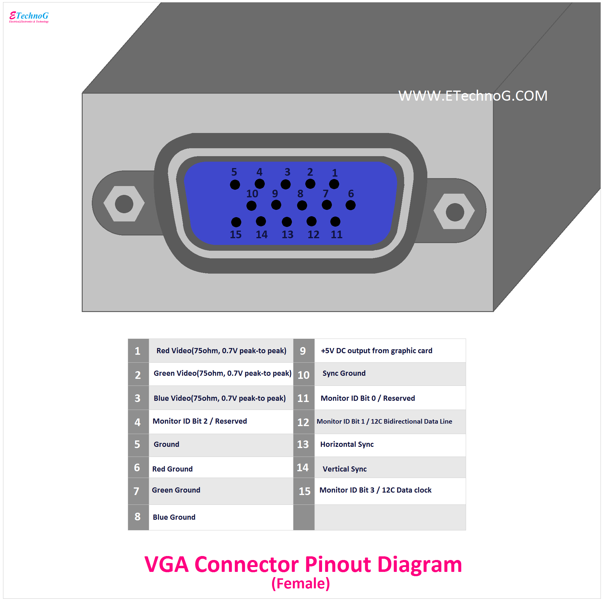
VGA, DVI, and HDMI Connector Pinout Diagram ETechnoG
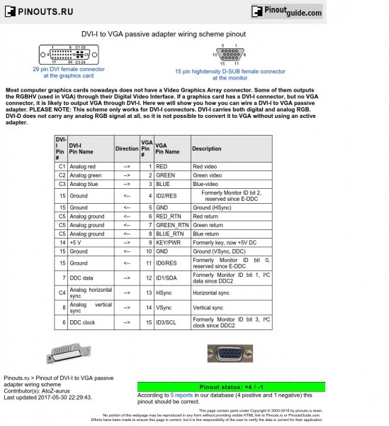
Pinout of VGA (15) connector and layout of 15 pin HIGHDENSITY D-SUB FEMALE connector and 15 pin HIGHDENSITY D-SUB MALE connector VGA (15) connector pinout layout schematic diagram add this page to bookmarks Nearly all modern PC graphics cards use the same 15 pin conenctor that the original IBM VGA card used.
Bestio Vga To Hdmi Cable Wiring Diagram
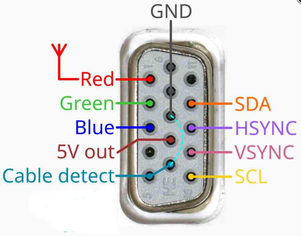
IBM designed two VGA connectors, one with five pins per row and one with three pins per row. D-subminiature is the version with three hooks. The D-sub version is commonly found on older computers, VGA cables, and displays. DB-15 is the standard five-pin row version. Pin Configuration of VGA Pin1 (RED): Red video (75 ohms, 0.7V peak-to-peak)

[DIAGRAM] 9 Pin Vga Wire Diagram
Nearly all modern PC that have a VGA connector use the same 15 pin VGA connector that the original IBM VGA card used. - Pete Kirkham - Butzke
Breadboard Due VGA library
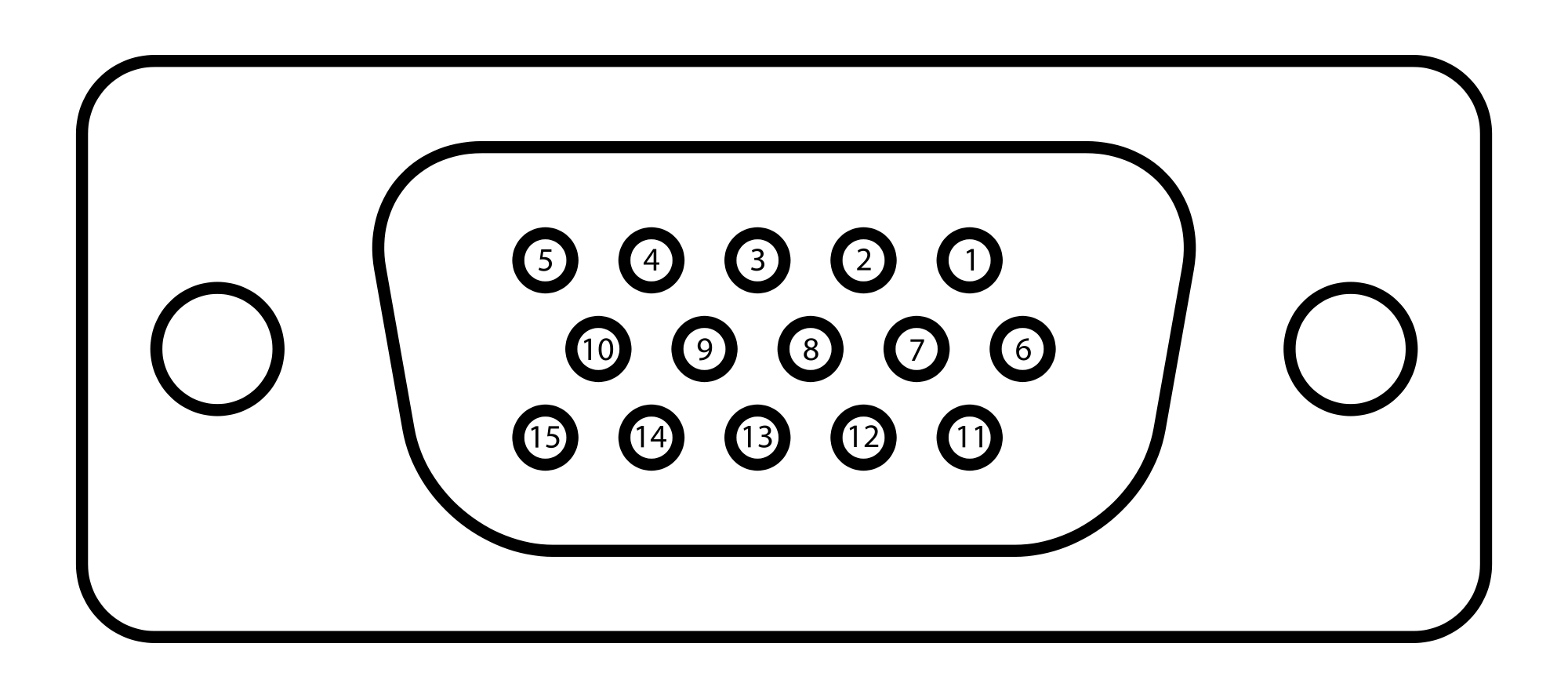
VGA connector pinout. "A Video Graphics Array (VGA) connector is a three-row 15-pin DE-15 connector. The 15-pin VGA connector is found on many video cards, computer monitors, and high definition television sets. On laptop computers or other small devices, a mini-VGA port is sometimes used in place of the full-sized VGA connector.
So schließen Sie einen CRTVGAMonitor an eine moderne Grafikkarte an ITIGIC
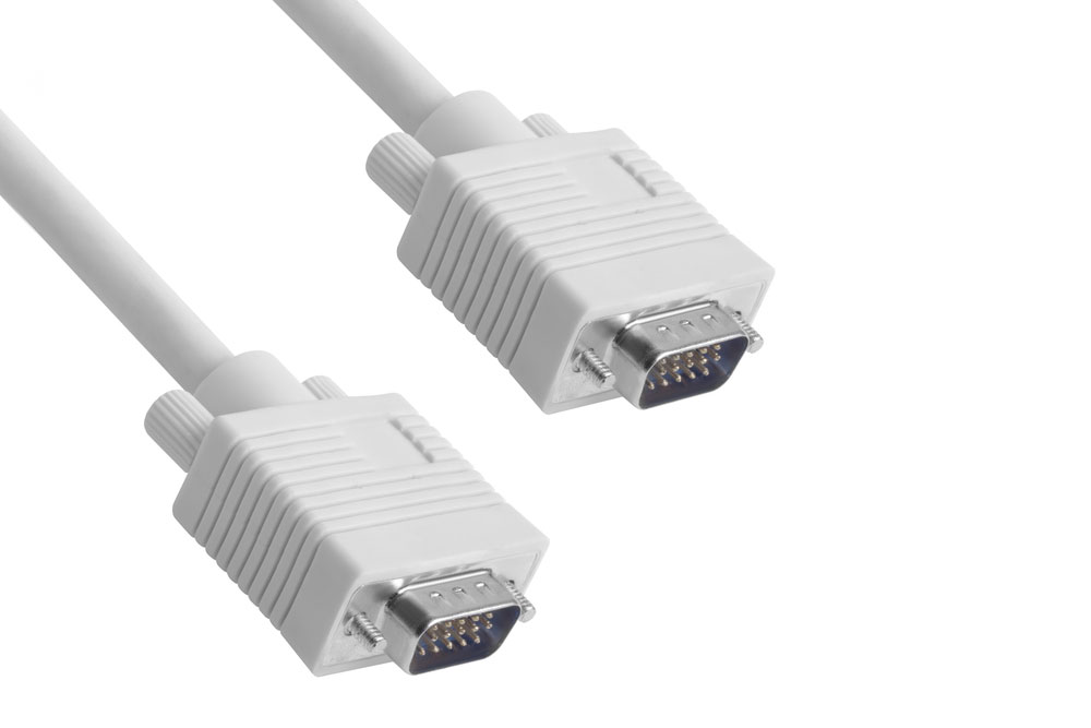
The most familiar and easy way to identify a VGA cable is the classic three-row, 15-pin connector (designated DE-15, and commonly referred to as D-sub miniature or D-sub) at either end. These connectors can be either male or female, and are commonly - but not always - flanked by a matching pair of captive thumb screws.

RS232 vs VGA Key Differences Revealed
For the VGA output, we use a parallel 24-bit RGB bus from the FPGA to drive a DAC. An R2R DAC of this size would be unwieldy, so I decided to use a GM7123C chip. This chip consists of three 10-bit.

VGA Full Form VGA Cable की जानकारी हिंदी में
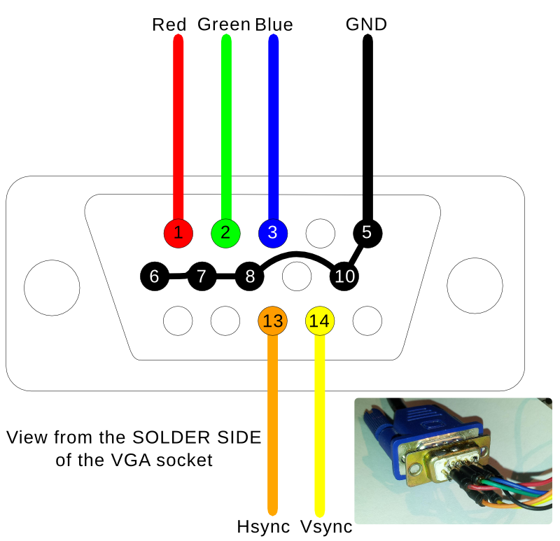
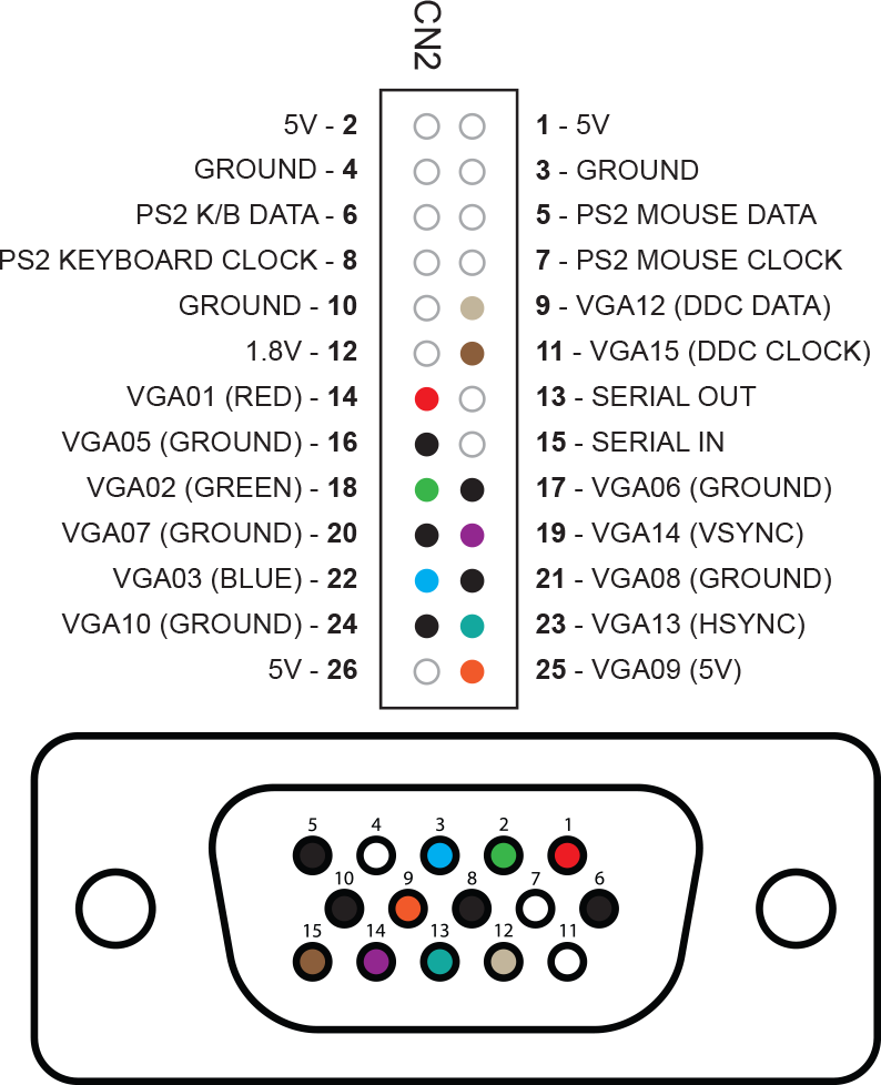
If its simply connecting a VGA connector then you will find a VGA wiring diagram here. I would not rely on the colour of the wires. Each manufacturer may have used a different colour code. However, if you know what each wire "does", the German Wikipedia article has a VGA pinout. Translating from that article:
VGA Connector Pinout What You Need to Know About the VGA Connector Pinout
November 25, 2022 by Kanishk Godiyal Video Graphics Array (VGA) is a display standard that carries video signals as analog components. IBM developed it in 1987 to use in their PCs (PS/2). The VGA connectors are usually used to connect a computer to a Monitor or projector, provided, the computer has a VGA port. VGA Pinout
VGA Pinout
The Video Graphics Array ( VGA) connector is a standard connector used for computer video output. Originating with the 1987 IBM PS/2 and its VGA graphics system, the 15-pin connector went on to become ubiquitous on PCs, [1] as well as many monitors, projectors and high-definition television sets.
Vga Pin Layout
The pin configuration of a VGA Connector includes 15 pins where each pin & its function is discussed below. VGA Connector Pin Configuration Pin1 (RED): Red video (75 ohm, 0.7V peak-to-peak) Pin2 (GREEN): Green video Pin3 (BLUE): Blue video Pin4 (ID2 / RES) : Monitor ID Bit-2 or Reserved Pin5 (GND): Ground Pin Pin6 (RGND): Red Ground
Av To Vga Wiring Diagram Blogid
Pinout of VGA (VESA DDC) and layout of 15 pin highdensity D-SUB female connector and 15 pin highdensity D-SUB male connectorVGA=Video Graphics adapter or Video Graphics Array.. This uses pin 12 on the 15-pin "VGA" connector as a data line. DDC2B - Adds clock (pin 15) and return (pin 11) to enable at least ID information to be obtained via an.

Diy Hdmi To Vga Wiring Diagram Upgreen
The VGA connector pinout has been around for many years and is the standard analog computer video output. It's also an easy way to get sound from your computer speakers. But what are all those pins? A VGA connector is a 15-pin D-shaped plug with three rows of five pins.
VGA D15 Pinout Projection Design Bootcamp
Brief Description VGA is a popular display standard, stands for Video Graphics Array. It was first proposed by IBM in 1987. It's a three row 15 pin connector comes with a screw type locking mechanism. A VGA cable carries analog components RGBHV video signal (Red, Green, Blue, Horizontal sync, Vertical Sync) and DDC data.